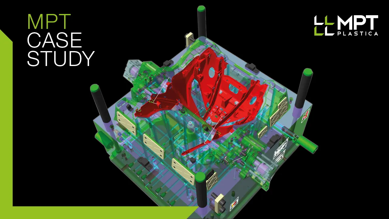
From draft angles to the injection point: the industrialization path of an open, articulated geometry
In the co-design of an automotive shield, an apparently minor modification involved mold closures, undercuts, radii, filling flows and the final geometry of the component.
Two 0.5 mm ribs opened up an entire design review. This is the starting point of this automotive front shield: a component that exceeds 650 mm in development and combines, in the same part, aesthetic surfaces, openings, structural ribs and assembly points. It is a frequent situation in the automotive sector, and it establishes an essential condition: a local variation rarely remains confined to the area in which it is introduced.
In the project of an automotive front shield, the industrialization path started precisely from here: from the systematic analysis of the relationships between the different areas of the CAD model.
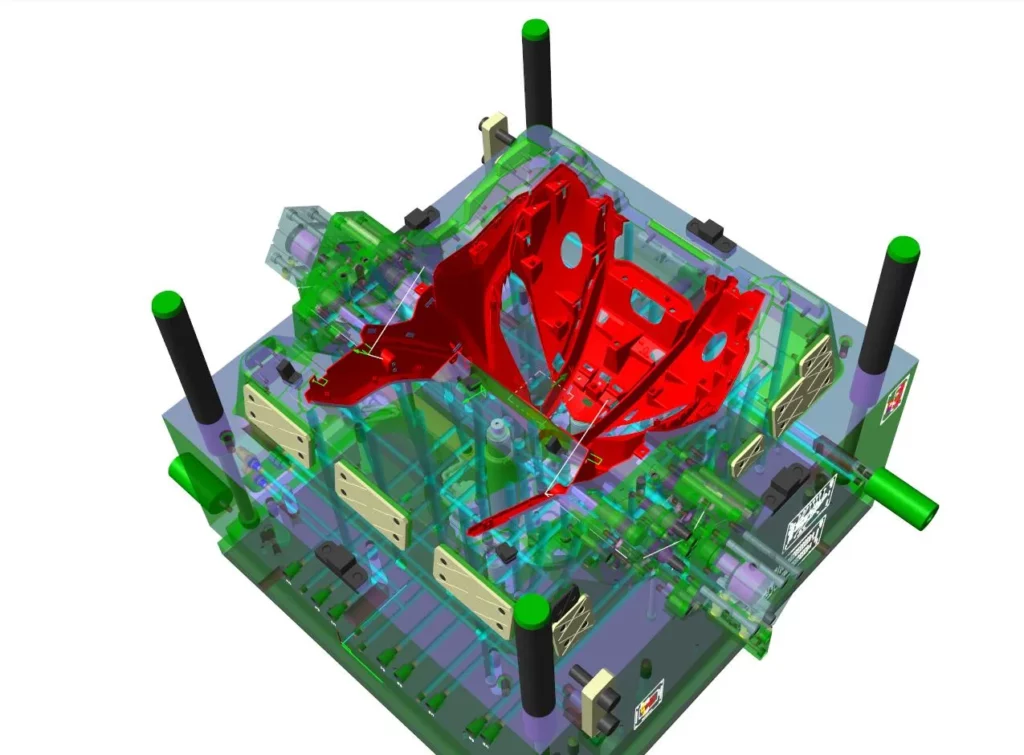
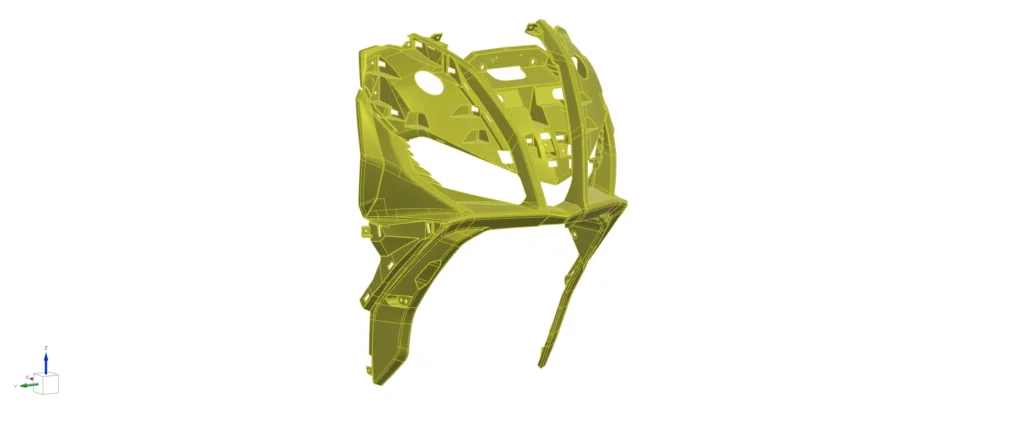
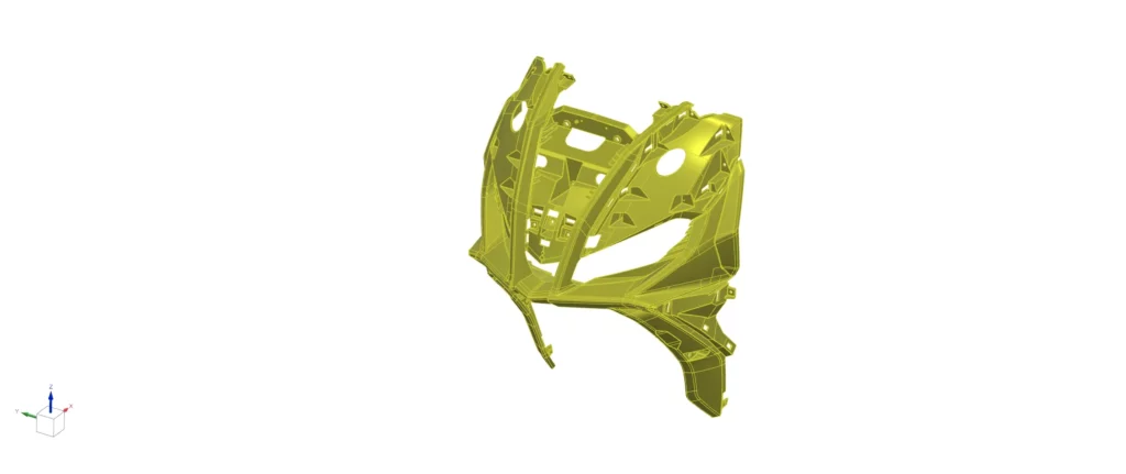
With dimensions of approximately 556 x 681 x 405 mm and a part volume of 1,237 cm³, the component featured numerous deep surfaces, extended openings and zones with different requirements from one another.
Draft angle analysis on deep walls and internal recesses
The influence of a wall on draft angles often goes beyond its own area. The technical review highlighted several zones without draft, walls that required different values and areas that would have required further design checks. In some cases, the introduction of 1° was requested, in others 0.25°, while some side walls were brought to 3° to allow correct mold closures.
Each variation in draft angles simultaneously modified:
- the position of the mold parting lines;
- le superfici di chiusura;
- the presence of undercuts;
- the couplings with adjacent areas;
- the dimensions available in the surrounding zones.
For this reason, the analysis was not carried out wall by wall, but by verifying each modification within the context of the component. The same approach was adopted for the internal recesses, where some surfaces initially without draft were realigned to the geometries already present in the neighbouring areas.
Thin ribs and steel tips: criticality identified before steel cutting
Among the observations that emerged during the review, one situation was particularly significant.
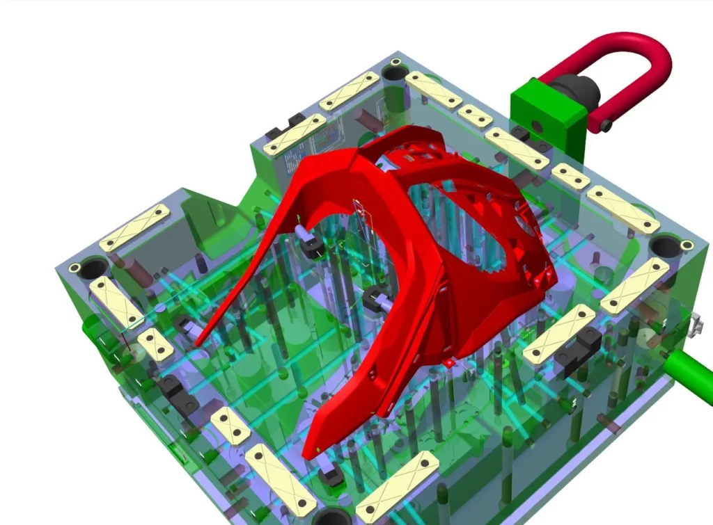
Two 0.5 mm ribs generated conditions considered critical for the mold. Such geometries would have produced particularly delicate portions of steel with implications both during the construction of the tooling and in the subsequent production phases.
The proposed solution was not a simple local modification. The analysis led to an evaluation of:
- the mating component;
- the actual function of the area;
- the possibility of eliminating some side portions;
- the reduction of thicknesses in the central areas.
This step provides a good example of one of the activities that characterize co-design: the criticality is not recorded as an anomaly but becomes the starting point for redefining the geometry in a way that is consistent with the behaviour required of the component.
Mold closures and undercuts: the work on the relationships between surfaces
Another significant part of the observations concerned the closures. The reviews include requests to revise the mold parting lines, to eliminate undercuts and to modify walls in order to improve closure conditions.
The introduction of R0.5 mm, R0.6 mm and R1 mm radii at specific points of the model responded precisely to this need. Because, in this case as well, correcting a single surface was not sufficient.
And the function of these fillets is not only geometric: it contributes to building more favourable conditions for the manufacturing and operation of the mold.
Moldflow simulation: verifying the behaviour of the geometry before mold construction
Once the geometry was consolidated, the project was supported by Moldflow simulations.
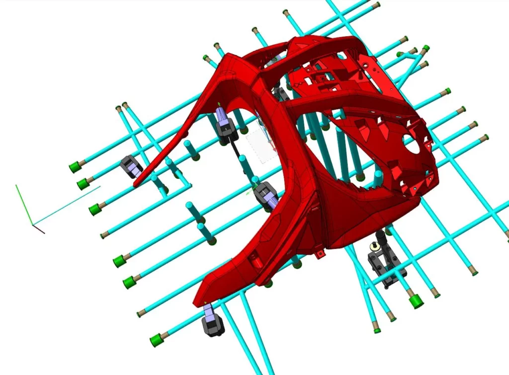
The model used included over 2 million mesh elements, with about 1.7 million elements dedicated to the component and more than 348 thousand to the feeding system. Such a dense mesh was needed to capture the behaviour of the flow in a geometry with extended openings and section variations, where a coarser model would have masked the criticalities.
The analyses concerned:
- flow front progression;
- pressure distribution;
- weld lines;
- air traps;
- material temperature during filling.
The simulation was carried out using PP Hifax TYC 459P, with a material temperature of 240 °C, a mold temperature of 50 °C and a filling time of 1.8 seconds.
These data made it possible to verify how the choices made during co-design were reflected in the behaviour of the component during the molding process. In particular, the analyses allowed us to observe the flow distribution along a geometry characterized by extended openings, section variations and different filling paths.
The injection point
The documentation also includes a specific check related to the injection area and the space available with respect to the surrounding components. It is an interesting step because it shows how the injection position is not defined exclusively on the basis of the simulation.
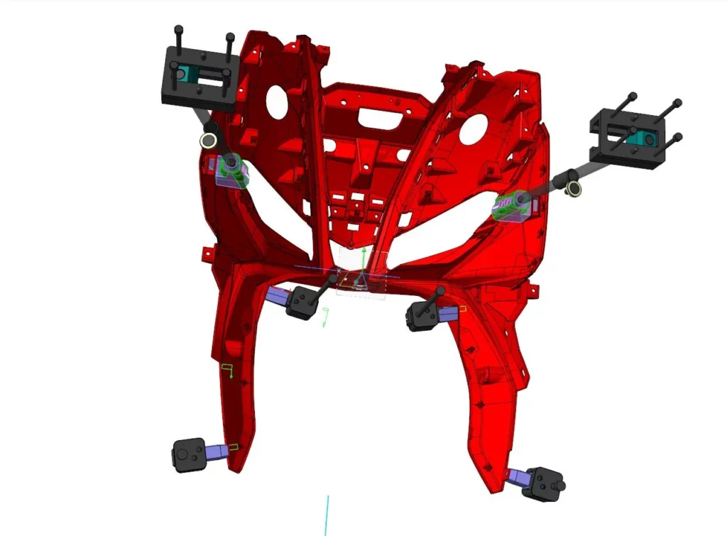
Within the project, it had to remain compatible with:
- the existing space constraints;
- the assembly requirements;
- the configuration of the surfaces;
- the behaviour of the flow inside the cavity.
The final choice is therefore the result of an evaluation that simultaneously involves product, process and tooling.
What to check before approving a complex geometry
The most interesting aspect of this project does not concern a specific technology or a particular mold configuration. It concerns the moment in which the criticalities are identified.
In the case analysed, most of the activities were concentrated before the construction of the tooling. And for those developing components characterized by extended surfaces, deep openings or articulated geometries, there are some questions worth asking before the final approval of the model:
- do all the walls have the necessary draft?
- are the closure lines consistent with the available geometry?
- are there sections that generate critical conditions in the mold?
- does the injection point remain compatible with all project constraints?
- do the modifications introduced in one area produce effects on other areas of the component?
These are checks that require time in the initial phases of the project, but they make it possible to approach the construction of the mold with a level of awareness that is very different from what can be obtained through a simple geometric validation.
If you are developing a technical component with extended surfaces, aesthetic requirements and complex assembly constraints, the dialogue between component design, simulation and mold design should begin before the final release of the CAD.
Let’s talk about it, let’s review your design needs together: https://www.mptsrl.it/en/contact-us/